Journal Article Reports on Modeling a Demand-Controlled Ventilation System in the Fire Dynamics Simulator
The peer-reviewed journal article “Modelling a Damper-Optimized Demand Control Ventilation System During a Fire” has recently been published in Fire Technology. Key findings from this report support the Fire Modeling Development and Validation research project, led by UL Research Institutes' Fire Safety Research Institute. Jason Floyd, principal research engineer, co-authored this paper with research engineer Dushaynt Chaudhari, as well as Christoph Meraner, Tarek Beji, and Janne Siren Fjærestad.
Understanding HVAC System Operations
Heat, ventilation, and air conditioning (HVAC) systems are essential to many buildings, such as residential, commercial, and industrial spaces. A primary purpose of many HVAC systems is to provide indoor air quality (filtration) and comfort (temperature and humidity). Typical HVAC systems have limited, fixed modes of operation. For example, they are either on or off, or the dampers in these systems are in an open or closed configuration. Such systems are not optimized for energy efficiency. This is commonly experienced on a hot and sunny summer’s day, where an HVAC system struggles to keep temperatures cool on the sun-exposed side of a building while other rooms end up too cold.
A more energy-efficient approach would be to divert more of the total flow to the sun-exposed rooms and less to the non-sun-exposed rooms. Such systems require sensors throughout a building, motorized flow control dampers (not just open or closed), and a control system to monitor sensors and adjust these dampers. Newer commercial construction is seeing an increase in the use of these systems.
HVAC Systems in Fire
Fire can have several impacts on an HVAC system. A fire will increase pressure in the compartment where it is located, causing the behavior of flows to change through the HVAC network. Soot produced by the fire can clog filters, resulting in a loss of total flow rate. Heat from the fire will be seen by temperature sensors and can impact the decision-making processes in the HVAC system’s control logic.
Modeling HVAC Systems
Typical computer models for HVAC systems do not attempt to model all the details of flow inside the system. Instead, the connectivity of the system is modeled, and simple one-dimensional equations are used to determine the system flows. An important parameter in this approach is how much resistance the air flow encounters as it moves through components of the HVAC system, such as the walls of a duct, elbows and tees, and filters. Some models do not account for temperature differences, as under normal conditions, temperatures in conditioned spaces in a residential or commercial building will be in a narrow range. Similarly, some models do not account for room-to-room pressure differences but only pressure drops inside the duct network, as in a typical building, pressures do not vary greatly from room to room under normal conditions.
More complex models will account for temperature and pressure effects. The HVAC model embedded in Fire Dynamics Simulator (FDS) is an example of such a model. FDS is a computational fluid dynamics (CFD) code used to model the effects of fire on the built environment.
FDS HVAC Model Validation
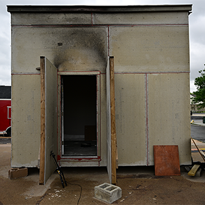
The FDS HVAC model has undergone a range of verification and validation exercises. These have all, however, involved HVAC systems with a single mode of operation. High-quality, experimental data on more complex systems had not been available. Recently, RISE Fire Research in Norway conducted a series of 14 experiments with a demand-controlled ventilation system in a real-scale three-room structure intended to be representative of a school. The experiments, called BRAVENT, included detailed measurements of flow rates in the system, the response of the control system (e.g., damper positions), and measurements of temperature and gas concentrations in the HVAC system and in the structure. This provided an opportunity to determine if the FDS HVAC model was capable of modeling a dynamically controlled HVAC system.
This paper used FDS 6.9.1 to model one of the tests from the BRAVENT test series. The modeling effort examined sensitivities to input parameters and the modeling approach to handling the flow rates in the HVAC system. The effort concluded that the FDS HVAC model had the capability of modeling the behavior of a dynamically controlled HVAC system, provided sufficient information is available on the dynamic components of the system.
For additional details regarding experimental setup, results, discussion, and more, read the full paper below.
“This was a challenging experiment to model. Key input data was unavailable or not available with good time resolution. Even with those challenges, FDS was able to model the complex HVAC system behavior resulting from damper position changes during a fire and to predict compartment flows and temperatures.”
—Jason Floyd
Principal Research Engineer
UL Research Institutes | Fire Safety Research Institute